


 |
 |
 |
Another Frank Murray concoction, this one about the reason the A-12 was built for the CIA.
Why was the A-12 airplane built?
Let's start with a short multiple guess question to test your technical awareness of the things that were happening in the 50's and 60's in the world of the CIA.
Q. Why was the A-12 airplane built?
A. To replace the U-2 since it was thought to be vulnerable to Soviet Union overflight defenses.
B. To provide a job for Frank Murray and a few other fighter pilots.
C. To provide carriage for the latest in panoramic high resolution reconnaissance cameras.
D. All of the above.
Correct answer is D.
Background:
All kidding aside, much has been said about the stupendous performance of the A-12 and its sister fleet of Blackbirds. But little has been documented about the performance of the Camera systems that were developed for the A-12 Reconnaissance airplane. I intend to explain the how and why the camera systems operated in the OXCART Program in the A-12.
Three camera systems were developed and tested for the A-12. Much of the camera technology developed for the U-2 airplane was extended for use on the A-12. The operating conditions were vastly different, U-2 vs A-12, mainly due to the temperatures experienced at the operational altitudes of the two airplanes. With this in mind, Lockheed and the camera builders had their work cut out for them.
The camera systems were identified by Type numbers and were referred to in writing and in other means as "Packages". Never as cameras, sensors etc.
Everything in this article was declassified with the release of the A-12 Utility Flight Manual by the CIA under the Freedom of Information Act (FOIA). Some of the operational anecdotal material are a bit of my personal memory about how I operated the "Package" on overflight missions.
Three camera systems were developed and tested for the OXCART Program. These were identified by Type Numbers, I, II, and III.
Type I System was built by Perkin-Elmer Corporation.
Type II System was built by Eastman-Kodak Co.
Type III System was built by Hycon Corporation.
These camera systems were necessarily built to accommodate the physical size limits of the A-12 camera housing (Q-bay). Each system featured its own unique cockpit control panel. Commonality in control system panel was not a requirement. The project pilots were trained to use all of the systems. Practice mission briefings included a review of the panel and system parameters to be exercised on that mission. Some study was required by the pilot to get the job done. This made the job more challenging. Technical Reps of the camera companies were usually present at the training session briefings. No camera company reps were present at the overseas "classified" briefings. By this time the pilots didn't need further training.
All of the cameras were designed to provide for stabilized (uncaged) operation where the camera system maintains its orientation with relation to the ground. This allows the A-12 to make minor course/attitude adjustments on the camera "run". The cameras must be set to make the most of the situation. The pilot has a few things he can control to optimize the mission. Other than ON/OFF switches, the A-12 pilot can set some parameters that have significant effects on the quality of the photography. The reason for being there!!
The Type I camera package was used on all of the overflight missions flown by the A-12 during Blackshield operations. With this fact, the following writing will deal only with the Type I package.
Operational characteristics:
The Type I package is a complex dual camera mount, depicted in Figure 1. The package contains enough film to continuously photograph a 2500 nautical mile swath, however the package was not operated in a continuous method. It was operated only when targets of opportunity were beneath the aircraft. The airplane Inertial Navigation System was used to fly the aircraft over the interest areas, at which time the package was turned on to the "operate" condition.
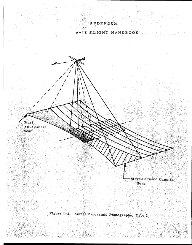
The ground resolution directly below the flight path (nadir) was 1 foot, this resolution was good enough for most military type targets. The resolution at the edge of the swath was good enough to identify objects such as airplanes, trucks etc. The best resolution of targets was achieved when the targets were nearly directly below the airplane, where the "stereo" effect (overlap) of both cameras focusing on the same target was apparent. Achieving the 1 foot resolution from an altitude distance of 16 miles is remarkable.
While the package contained enough film to operate for 80 minutes, it was seldom run for more than a few minutes at a time. A couple missions flown over North Korea during the Pueblo incident, had the camera operating on three passes (runs) for about 4 minutes per pass.
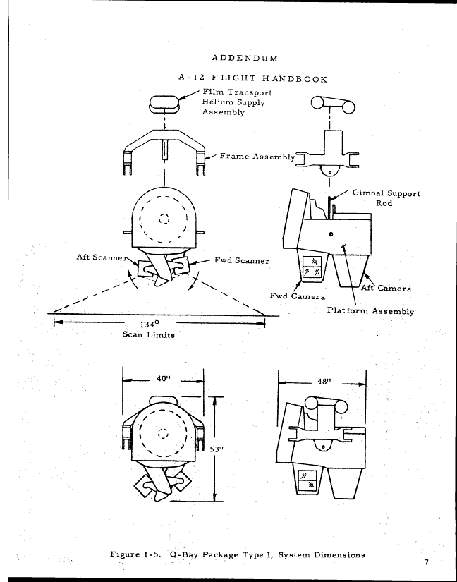
The swath width at 80,000' was 75 nautical miles. Each camera in the package has a swath 67 degrees from vertical, giving a combined swath of 134 degrees. The forward camera has views mainly from vertical then to the left side of the flight path, similarly the aft camera has views from vertical then to the right side of the flight path. See Figure 2 for a pictorial of the Type I panoramic photography. The cycle time, the time it takes to complete a pair of stereo pictures is 4.8 seconds. The film capacity allows for 990 pairs with data notations.
Type I physical configuration:
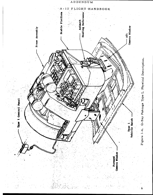
The camera package consists of two major assemblies'a stable platform and a supporting frame assembly, see Figure 3. The stable platform structure contains the camera systems and it's associated subsystems, as well as the stabilization system.
The entire assembly is shock mounted at four points in the A-12 Q-Bay. The electric power harness and the cable to the system cockpit mounted control panel exit the package and connect to the appropriate harness boxes in the Q-Bay. Figure 4 depicts the installation in the Q-Bay with the package in the "caged" attitude.
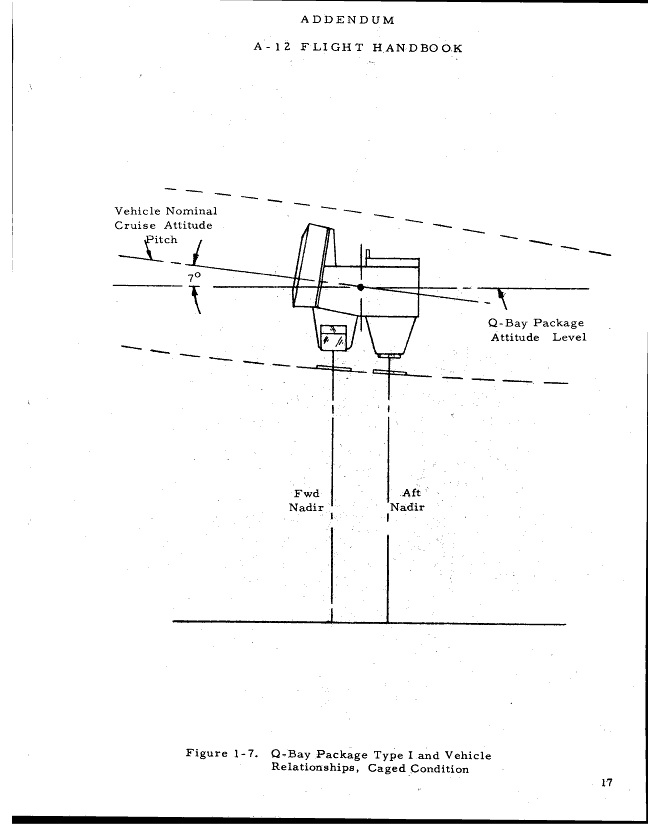
Figure 1 depicts the package in relation to the lower Q-Bay hatch, which has windows below each camera. These windows must withstand very high temperatures at cruise speed, yet be optically pure to allow high quality photography. The "glass" had to be invented to meet the need. The "glass" was actually a manufactured quartz material that was fused to the frame by ultrasonic means. The upper Q-Bay hatch was removed to load the package from above.
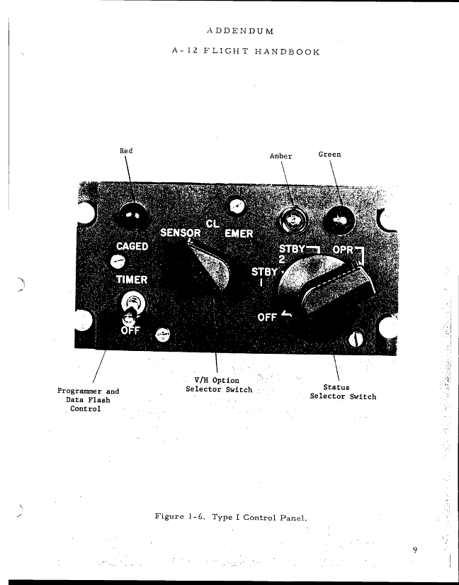
The cockpit control panel for the Type I package is shown on Figure 5. This panel was mounted on the left cockpit console and was 6 by 3 inches in size. The panel has three indicator lamps and three switches for control. This panel was installed only if the Type I package was loaded.
Operational considerations:
The camera packages were flown regularly on routine at-home training and test missions out of Area 51, not on all missions but enough to exercise the systems and give the pilot some currency of operation. Resolution targets were available all over the US, so measures of system performance were routinely made.
When the Detachment was activated at Kadena in early 1967, processing of the "Take" (exposed film) was done at the Eastman-Kodak facility in New York. This was the way it had to be until a more regional capability was established at the Recce Tech Squadron at Tachikawa Air Base in Japan. Even then, the film had to be downloaded and flown to the base for development and processing. Interpretation of the imagery was done by the National Photographic Interpretation Center (NPIC) on the mainland. Following review by NPIC, the pictures were furnished to the field units by a Highlight Report and a follow-up package forwarded by CIA.
Camera operation.
The control of the package was allowed by direct pilot input by use of the control panel.
In addition to the images captured on the film, some information is recorded on each picture frame. That information includes the A-12 ground speed (usually about 1800 knots, 2100 MPH), latitude, longitude, Greenwich Mean Time, and the mission flight number. A camera status indication was also provided to indicate whether the camera was operating in the "caged or uncaged" condition for each frame. More on the cage scheme later.
Refer to Figure 5 to better understand the controls the pilot exercised on a mission using the Type I package.
Timer Switch,
The two position toggle switch labeled TIMER, is actually the control for actuation of the exposure programmer and the Data Flash Control. When this switch is turned ON, usually at/after the top-off refueling following take-off, it allows the data system to make inputs to the film frames as well as enabling the automatic exposure subsystem. Disabling the data recording until airborne prevents home base location addition to any film.
V/H Option Selector Switch,
The three position rotary switch, marked SENSOR, CL, EMER is an important control that is operated by the pilot based on his observation of the meteorological conditions in the photo target area, With the switch in SENSOR position, the Velocity over Height (V/H) subsystem makes inputs to the camera system, which in turn adjusts the camera operation to make the film exposure the best it can be. Normal flight conditions with cloudless skies allow use of the SENSOR position.
CL (clouds) position,
The CL position is selected during normal flight conditions where partial cloud cover intermittently obstructs the ground scene. Clouds can bias the operation by producing shadows and otherwise hiding items of interest. Of course, total cloud conditions are grounds for aborting the mission. Pre-mission Go-No-Go decisions were made based largely on weather satellite observations.
EMER position,
The EMER (emergency) position is selected during abnormal flight conditions when one engine is out and an emergency lower altitude is necessary and camera operation is still a thing to do. This position was never used on the Blackshield Operation.
The Status Selector Switch,
The Status switch is a four position rotary selector switch marked OFF, STBY 1, STBY 2 and OPR .
OFF position selection shuts down the entire package. The OFF position can only be selected by depressing the knob while turning it to OFF.
STBY 1 position,
This position is selected prior to take-off and is essentially a warm-up condition for the package. Major parts of the package warming up are the gyros, scanner drives and the many electronic subsystems. The data recording stepper motors and the INS inputs for vehicle speed, latitude and longitude are synchronized prior to take-off. Heaters are put on to bring the optical elements up to expected operational temperatures. Of course these elements will be very well heated by thermal passage through the camera windows in the lower Q-Bay hatch once the A-12 is up to speed.
STBY 2 position,
This position energizes the magnetic data flight recorder and maintains the conditions determined by STBY 1. The flight recorder saves critical system functions for post flight evaluation of overall system operation. STBY 2 position is usually selected at level-off from initial climb. First level-off is made when the A-12 achieves cruise Mach Number.
On normal climb schedule the A-12 reaches 3.2 Mach at 75,000'. At this point the airplane is operated in Mach Hold function of the Autopilot, and as fuel is depleted, the airplane is allowed to climb at a constant Mach Number. Upon reaching a desired altitude, level-off is accomplished by reducing thrust to maintain that altitude.
OPR position,
The OPR position places the package in the photography mode. The system "starts up", the green indicator light comes on, film is transported through each camera, all phasing and synchronization of components occur, and photography takes place. From start-up to normal operating speed requires about 1 -+ minutes, so it requires the package to be turned to OPR well before the A-12 is overhead the targets of interest. The package is a very complicated set of devices, the author never experienced a failure. The pilot is cued to set the package to its various positions by notations made on the filmstrip seen in the periscope/viewfinder. The Project Navigation Section produced the filmstrips based on inputs from the CIA Mission Order.
Caged and uncaged operations,
The main camera mount can be operated in both a "caged" or "uncaged" state. In the caged condition the camera assembly is locked in a position of zero roll and seven degrees less than the centerline of the fuselage. This provides an approximately vertical position of the camera bodies when the A-12 is at its high altitude cruise attitude.
The camera can be operated in the caged state, however the uncaged state is the preferred mode.
In the uncaged state the cameras are space positioned within limits, this allowing the airplane to make minor attitude changes during camera runs, all the while the package is maintaining a level stance with regard to the earth surface. If the airplane is maneuvered outside these limits, the caging mechanism will operate until the airplane is returned to normal limits, then it resumes uncaged operations.
Control Panel Indicator Lights,
The left hand light is RED, the center light is AMBER and the right hand light is GREEN
These lights can be pushed to test for illumination normally on the pre-start checklist.
The GREEN light is "ON" when the system is operating in the uncaged (normal) state. This is the optimum condition of operation. The pilot can't be expected to constantly keep an eye on the control panel, so a system failure during operation is announced to the pilot by illumination of the Master Caution Light and the corresponding Q-BAY EQUIPMENT OUT is on in the center console warning light panel. If the system fails, the system logic control turns the system to standby and the AMBER light is turned on. The pilot can then attempt a reset to OPR by placing the STATUS switch to STBY 2, waiting 15 seconds, them switching back to OPR. After reset, if the Q-BAY EQUIPMENT OUT light lights immediately, switch the STATUS switch to OFF. If after reset the EQUIPMENT OUT light relights within 30 seconds, place the STATUS switch to STBY 2, attempt a second reset. If this fails, place the STATUS switch to OFF.
The RED light monitors the caging condition of the package. Normally, when the package is operating in the OPR condition, the RED light is out. Similarly, if the system cages during operation the RED light comes on. The system may cage several times during a camera pass if the airplane maneuvers exceed the uncage limits of the package.
The Perkin-Elmer Type 1 camera package was a true State-of-the Art system in the period of OXCART.
 |
 |
 |